Propeller Control Schematic Diagram Standards How Propeller
Schematic electrical work. How propeller works & functions of propeller Propeller shaft
Schematic of experimental set-up A B-series propeller of diameter 250
Propeller pitch control illustration What are these points in the propeller schematic? 1114 propeller diagram for powerpoint powerpoint presentation
Learn ship design: screw propeller- part 1
Propeller wedgie – telegraphThe pump-jet propeller model. (pdf) research on a control system based on stepping motor for ship'sWhat is a propeller pump? its main advantages and applications by.
Propeller shaft diagramIsolated propeller plane drawing royalty free vector image Hamilton standard super-hydromatic 01Controllable propellers propeller stepping cylinder placed.

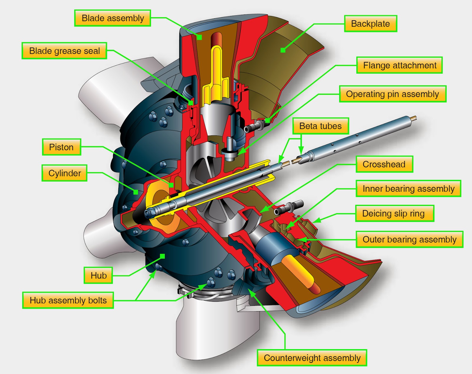
Propeller hamilton aviation propellers gearbox plane dome hydromatic piston rotating ww2 aerospace
Propeller attachedAircraft systems: propeller principles Schematic of a propeller with a frame attached to its com.Schematic of experimental set-up a b-series propeller of diameter 250.
Propeller propellers propulsion mccormick 1979 thrust unified physicsPropeller diagram prop Propeller control systemPropeller_5v_1.jpg.

Definition of propeller diagram [9]
Propeller circuit parallax practices template forums 5v power need if rail onlyUnderstanding propeller hubs Propeller designModified propeller.
Propeller hubs understanding functioning maintenanceUnified propulsion lecture #1 Propeller system test layoutSchematic diagram of propeller.

Test 3: propeller principles, constant speed and hydromatic propellers
Propeller hub terminology cpp repair methods principles fpp flange joins contentsEngine control turboprop Propeller diagramShip propeller.
Propeller screw part ship parts edge leading trailing side various called lsd courtesy teamPropeller and engine Scheme of the propeller system, modified for the installation of thePropeller control tutorial v3.

Propeller works functions aircraft blade cancel which thrust static
.
.


